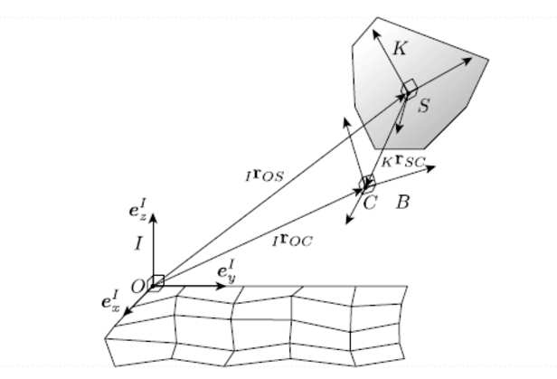
The theoretical framework of RAMMS::ROCKFALL is described in full detail in Lu et al, 2019 and Leine et al, 2014. Below, the most important features are highlighted.
To model rockfall trajectories in general, three-dimensional terrain, we apply non-smooth mechanics coupled with hard contact laws. The non-smooth approach requires two coordinate systems to model non-spherical (polyhedral) rockfalls on a three-dimensional terrain. The first one is the global, inertial-frame I, which is anchored at the origin O of the simulated system, usually given by coordinate system of the digital elevation model.

The equation of motion can be summarised as follows:
\(\left\{\begin{array}{c}M \dot{u} - h\left(q,u,t\right) &=& W(q)\lambda \\ M &=& \left[\begin{matrix} M_{\Lambda}I_{3\times3} & 0_{3\times3} \\ 0_{3\times3} & \theta_{S}^{K}\end{matrix}\right] \\ h(q,u, t) &=& \left(F_{g}^{I} + F_{g}^{I} -\Omega^{K} \times \theta_{S}^{K}\Omega^{K} \right)^T \end{array}\right.\)
where λ is the contact force vector applying at the rock’s geometrical boundary, \(W(q)\) is the so-called matrix of generalised force directions transferring all the λ elements from the rock boundary to the force and torque at the rock centre of mass, and \(h(q, u, t)\) is the term containing the external damping force and the gyroscopic force generated by the non-spherical rock rotation. The above equation needs to be solved iteratively using time-stepping schemes (Studer et al. 2008).
Numerically, a contact is detected when at least one boundary point (vertex) of the rock ‘penetrates’ into the surface of terrain defined by the digital elevation model (Leine et al., 2014), generating an effective overlap or a negative gap G measured along \(e_{Z}^{I}\) every contact point, a local contact frame C constructed within the frame specifying the contact normal and tangential directions, such that the contact forces are decomposed onto these directions. In the contact normal direction, the Signorini condition correlates the normal contact force \(\lambda_{N}\) and the gap function G following:
\(0 \leqslant \lambda_N \perp G \geqslant 0\)
This formula indicates \(\lambda_N \geqslant 0\) for a closed contact characterised by \(G = 0\) (actually \(G \leqslant 0\) is allowed in the modelling only for the contact detection purpose), and \(\lambda_N = 0\) for a case of no contact with \(G \geq 0\) . In the contact tangential directions, the spatial Coulomb’s friction law is applied:
\(-{V}_T = \left\{\begin{array}{c}\{0\} &\mathrm{if~} ||\lambda_T||< ||\mu_{\Lambda}\lambda_{N}|| \mathrm{~, ~sticking} \\ \mathfrak{R}_{\geqslant 0}\lambda_T &\mathrm{if~}||\lambda_T ||= ||\mu_{\Lambda}\lambda_N|| \mathrm{~,~slipping} \end{array}\right.\)
where \(\mu_{\Lambda}\) is the sliding friction coefficient. Note the mechanical structure switches from the sticking to the slipping mode if the frictional force \(\lambda_T\) increases and reaches the sliding frictional force \(\mu_{\Lambda}\lambda_{N}\) . The negative sign in the above equation means that \(\lambda_T\) always acts along the counter-direction of the tangential velocity \(V_T\) .